The Steam Catapult
Commander (E) W. R. Stewart, A.M.I.Mech.E., M.I.Mar.E., R.N.
Introduction
As readers of this Journal will be aware, the catapult has, in recent years, become of ever greater importance in the operation of aircraft from carriers and, unless some radical change in the characteristics of aircraft becomes possible and is made, it appears that this importance will continue. Aircraft are now coming into service which cannot be expected to make a free take-off from a carrier deck under normal operational conditions. They require assisted take-off; that is, the application of some force additional to the thrust of the aircraft engines to accelerate them rapidly to flying speed. At present the only known methods of achieving this are either jettisonable rockets attached to the aircraft or the use of the mechanical towing force of a catapult. Of these the latter is favoured as being easier and more economical to use. The situation outlined has arisen because of the penalties on aircraft performance and endurance which would unavoidably follow from building the requisite free take-off characteristics into conventional type aircraft. The accepted policy is that aircraft performance should be conserved by providing aids to take-off and landing as part of the ship wherever practicable and possible.
Catapults and Existing Carriers
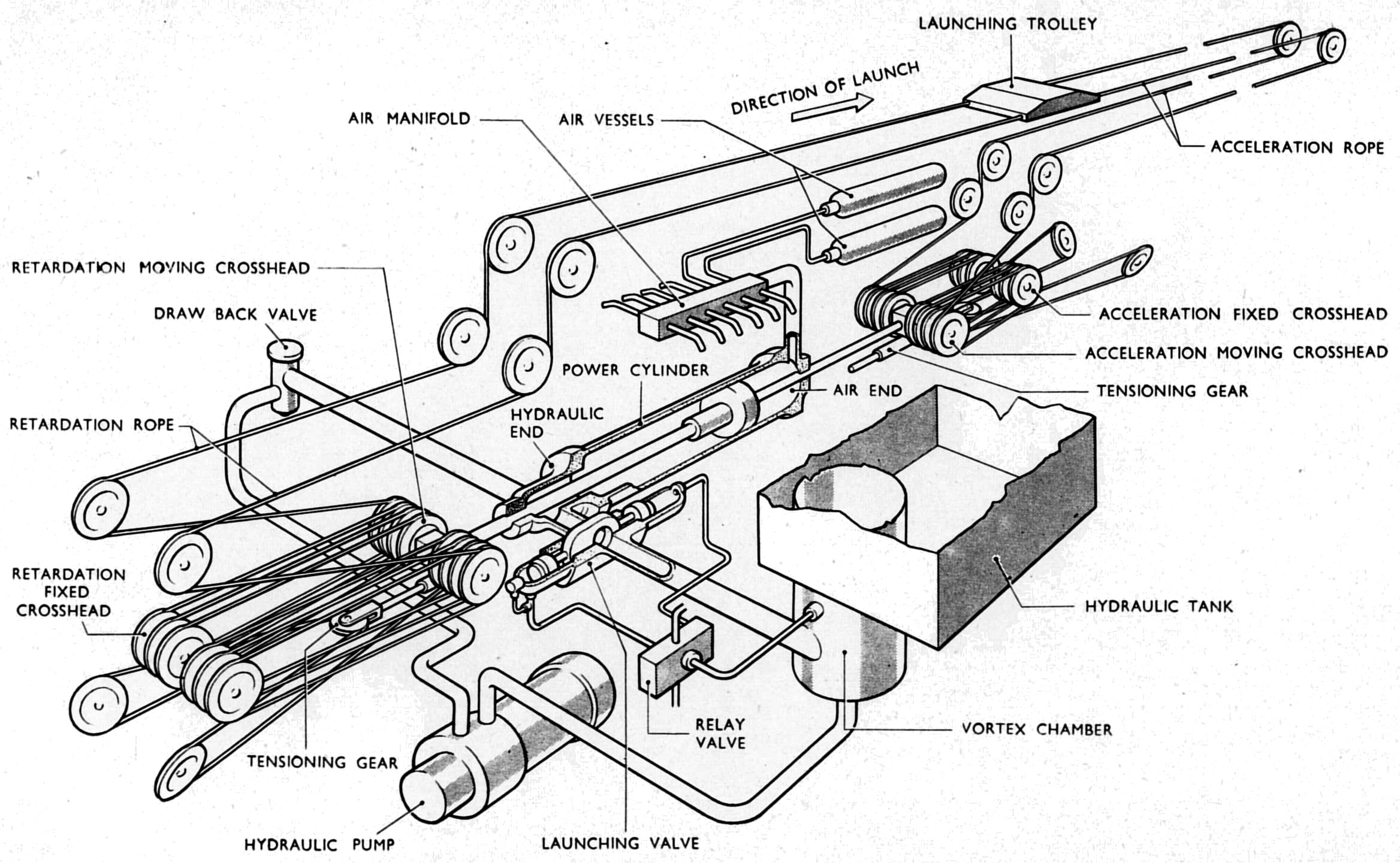
Fig. 1: Arrangement of a hydro-pneumatic catapult in an aircraft carrier
Click for enlargement.
All existing aircraft carriers in the Royal Navy and United States Navy have, up till now, used catapults of the hydro-pneumatic type. Very briefly, these catapults use the force of compressed air acting on a piston to accelerate the aircraft. The piston is connected by ropes running over pulley wheels to a bogie, or shuttle, running on wheels or slide blocks in a deck track; the shuttle is connected to the aircraft by a bridle. The compressed air is stored in large steel air bottles and after each launch is re-compressed into the bottles by the piston which is forced back by hydraulic pressure on its other side; the pressure is supplied by large and powerful hydraulic pumps and is controlled by valves. In addition to the ropes connecting the piston and shuttle to transmit the launching force, further ropes are required, fixed to the after end of the shuttle to bring it rapidly to rest at the end of acceleration, and then to retract it to the firing position. A typical arrangement is shown in Fig. 1. These hydro-pneumatic catapults are heavy and complicated but have given satisfactory performance for a number of years. All existing R.N. aircraft carriers built during and prior to the late war have a hydro-pneumatic catapult of the mark designated BH3 which has proved adequate for piston engined fighters and strike aircraft in service to date. H.M.S. Eagle and other postwar carriers have two more powerful hydro-pneumatic catapults of the BH5 mark, giving some 20-25 knots greater end speed than the BH3, and with heavier aircraft.
The BH5 catapults were originally designed and built to meet a last war staff requirement; since then it has been found possible to increase their performance by the use of higher operating air and hydraulic pressures. After the war it became apparent that the new turbo-jet aircraft in prospect would require a catapult performance higher than that of the BH5, both as regards the weight of aircraft launched and the end speeds to be attained. Consideration was given to an even larger hydro-pneumatic catapult, but analysis showed that the forces involved would be very great, requiring very heavy parts to withstand them. This would be particularly undesirable in the case of the ropes, since these have to be accelerated to the full speed of the catapult and then sharply brought to rest at the end of the launch. For example, the ropes and other moving parts in a BH5 catapult are equivalent to a weight of 17,000 lb; this, in addition to the aircraft weight, has to be accelerated to full speed and then decelerated. In the case of a larger hydro-pneumatic catapult the situation would have been still worse and the position approached wherein it would take the catapult all its time to accelerate itself, let alone the aircraft.
The Slotted Cylinder Catapult
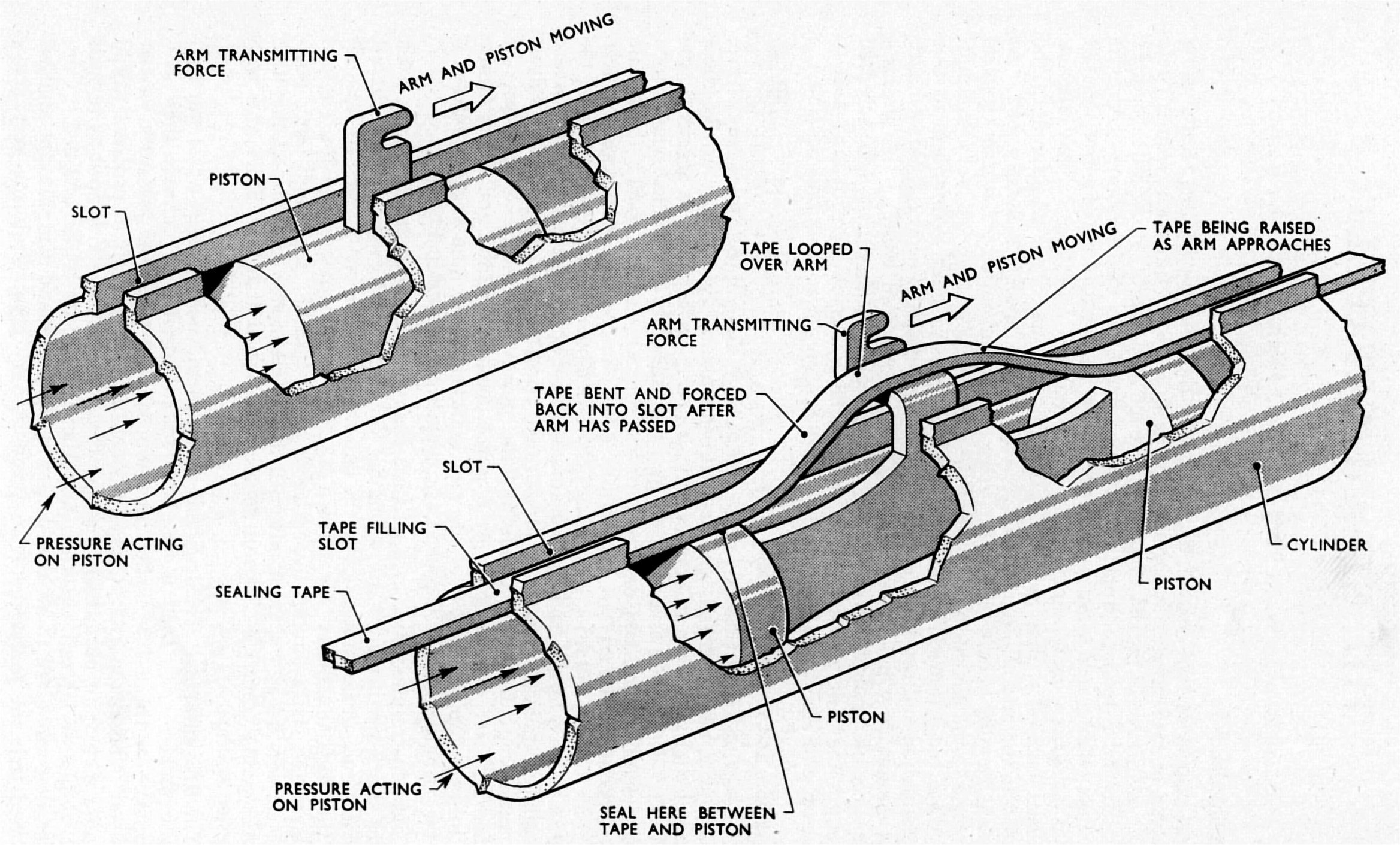
Fig 2.: Principle of slotted cylinder Click for enlargement.
In the circumstances it was necessary to find some alternative mechanism to the hydro-pneumatic cum rope catapult if the high catapult performances desirable from the aircraft designers' point of view were to be met. Various alternatives were considered and eventually it was decided to develop an arrangement based on the slotted cylinder, a device known for many years. Briefly, this consists of a simple piston in a cylinder, which is acted upon by steam or air, or any other convenient medium. In the usual piston and cylinder arrangement the force on the piston is transmitted by a piston rod attached to it, which comes out of the end of the cylinder, frequently through a gland. In the slotted cylinder the method of transmitting the force from the piston is different. A slot is cut along the whole length of the cylinder and an arm is attached to the piston which projects out through this slot. The force on the piston is transmitted through this arm and can therefore be applied to a catapult shuttle, or anything else, without the intermediary use of a long piston rod. This is illustrated in Fig. 2.
Of course the obvious problem is how to stop the steam or air, under pressure behind the piston, from merely rushing out through the slot and escaping. This is done by a device very simple in principle. Imagine that the piston is half way down the cylinder with the arm for transmitting the force projecting through the slot. Imagine too, that there is a length of steel tape with which to seal the slot. The best that could be done would be to fit the tape into the clear slot in front of and behind the piston, leaving a loop over the projecting arm and fitting the tape as snugly as possible up to the arm. If the piston was long enough it would extend beyond the looped part of the tape, so that steam behind the piston would find its escape blanked by the piston, and by the part of the tape fitting the slot-it would not be able to get to the part of the tape looped up round the projecting arm. If it is now wished to move the piston, all that is necessary is to pull up the tape in front of the projecting arm as it moves along, and press it down into the slot behind it, that is, to move the loop along with the piston keeping it just over the projecting arm (see Fig. 2). This is the principle of the slotted cylinder, but of course it is a big step to advance from the simple idea to a practical design. The great merit of the slotted cylinder is that the force on the piston is transmitted directly to the catapult shuttle, thus saving all the weight and space and heavy inertia of piston rods and ropes.
The decision to attempt to develop a slotted cylinder catapult for aircraft carriers was taken in 1946, and was influenced by the fact that the Germans in the last war had successfully developed and used slotted cylinder catapults for launching VI flying bombs. The German catapults used hydrogen peroxide to give the operating pressure in the cylinder; they were simple but very heavy and had many features which were not suitable for ship use, for instance the piston was not retarded at the end of the launch but shot off after the VI.
Design Problems
Many problems had to be solved to design a catapult which would be likely to be satisfactory for shipboard use. It was necessary first to devise a practical arrangement of the sealing tape. In practice this is a flexible steel strip, and suitable guides are provided on the piston to lift this over the arm from the piston projecting through the slot. A simple but ingenious arrangement was devised whereby the sealing strip, when in position, is made to serve to hold the two lips of the cylinder slot from opening out; this is essential since the long slot in the cylinder would naturally weaken its ability to withstand the internal pressure.
For shipboard use the loss of the piston with each shot could not be tolerated, so that some means of stopping it at the end of launch is required. This is no mean problem since each piston plus the attached shuttle weighs nearly a ton and must be brought to rest from, say, 120 knots in as short a distance as possible. It has been found possible to achieve this retardation in 5 ft. by fitting a tapered ram projecting from the front of each piston, which enters a thick and strong cylinder at the end of the catapult; the cylinder is kept full of water by jets, and the water escaping through the narrow gap between the ram and cylinder mouth reaches a very high pressure which brings the piston to rest. The maximum retardation achieved is of the order of 800 g.
Numerous other arrangements had to be devised, e.g. for bringing the pistons and shuttle back to the launching position, for securing positive and exact control of admission of steam to the cylinders to get the required launch characteristics, etc. Great attention has been paid to the control arrangements to secure that they should be foolproof in action and give sure, safe launching.
The BS4 Catapult for Aircraft Carriers
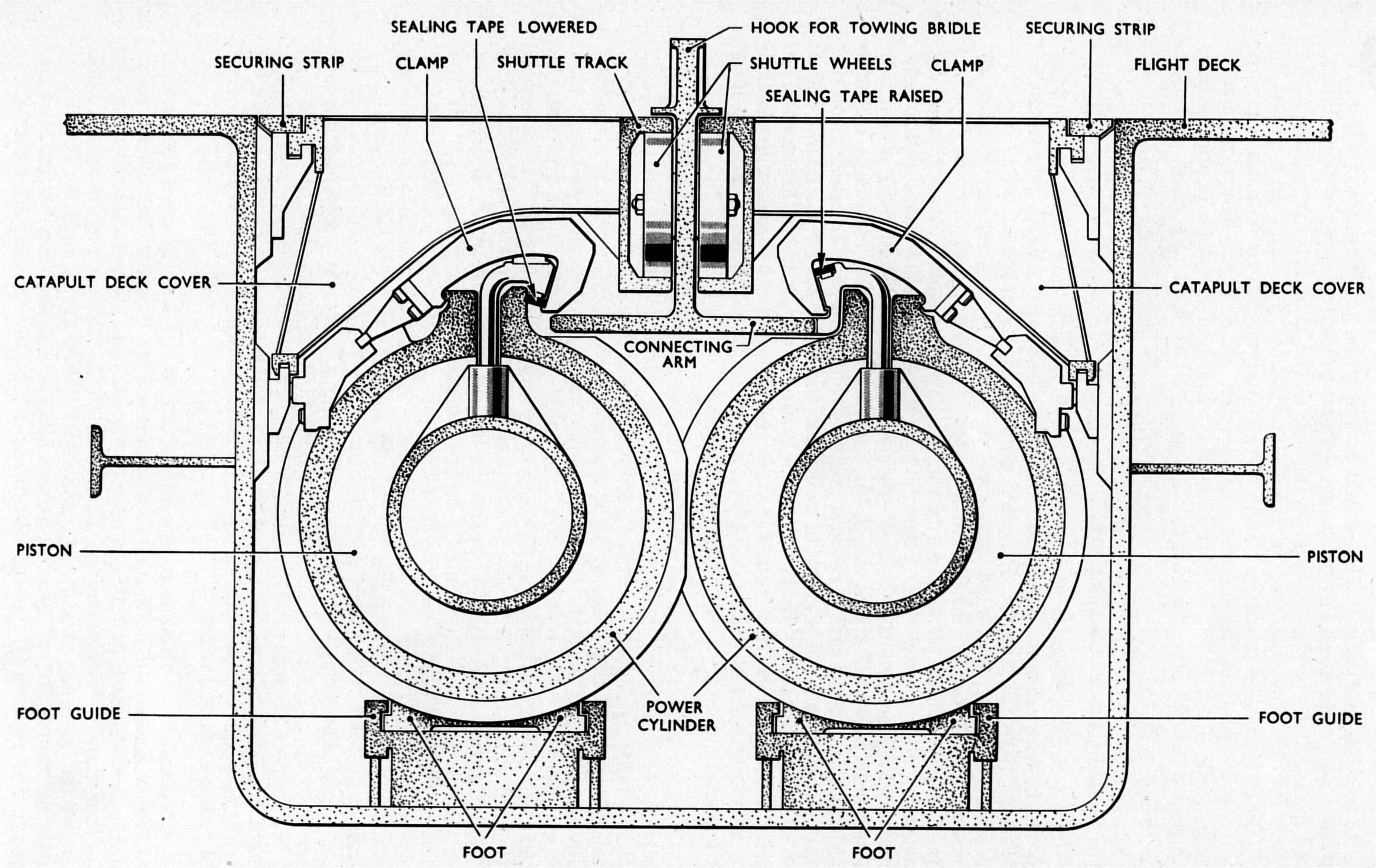
Fig. 4: Section through a B.S.4. catapult Click for enlargement.
The steam catapult, as now developed for fitting in H.M. aircraft carriers, and bearing the mark BS4, consists of two long slotted cylinders lying side by side in a trough immediately under the flight deck, and extending the whole length of the catapult runway. In each cylinder is a piston with an arm extending through the slot, driving a shuttle, common to both pistons, which runs in a track in the deck and tows the aircraft in the usual manner. (Fig. 4 shows a section through such an arrangement.) At the forward end of each cylinder is a water-filled retardation cylinder to bring the pistons and shuttle to rest. Steam for operating the catapult is stored in large receiver drums, two for each catapult; these are situated one or two decks below the after end of the catapult and are charged by steam supplied from the ship's main boilers. From the receiver drums large bore pipes take the steam to two launching valves, one on the after end of each cylinder; these control the admission of steam. At the end of a launch the launching valves are closed and a large exhaust valve opens to an exhaust pipe which discharges below the waterline. The control system and the machinery for working the various valves, and for retracting the pistons and shuttle ready for the next launch, are housed in a compartment immediately under the after end of the catapult. The actual firing of the catapult is in the hands of an operator at a deck control position. A typical layout is shown in Fig. 5.
The operating sequence is as follows. The pistons are brought to the after end of the cylinders and the receiver drums charged with steam. The aircraft is placed on the catapult in the normal way and the towing bridle and holdback fitted. Using a manoeuvring gear the pistons are moved forward to take up the slack in the bridle and tension up the holdback. On the signal from the directing officer the catapult is fired by opening the launch valves and admitting steam to the cylinder at a controlled rate. At the end of launch the launching valves are closed and the exhaust valve opened to empty the cylinders. The pistons and shuttle are retracted and the receiver drums recharged with steam from the ship's boilers ready for the next launch.
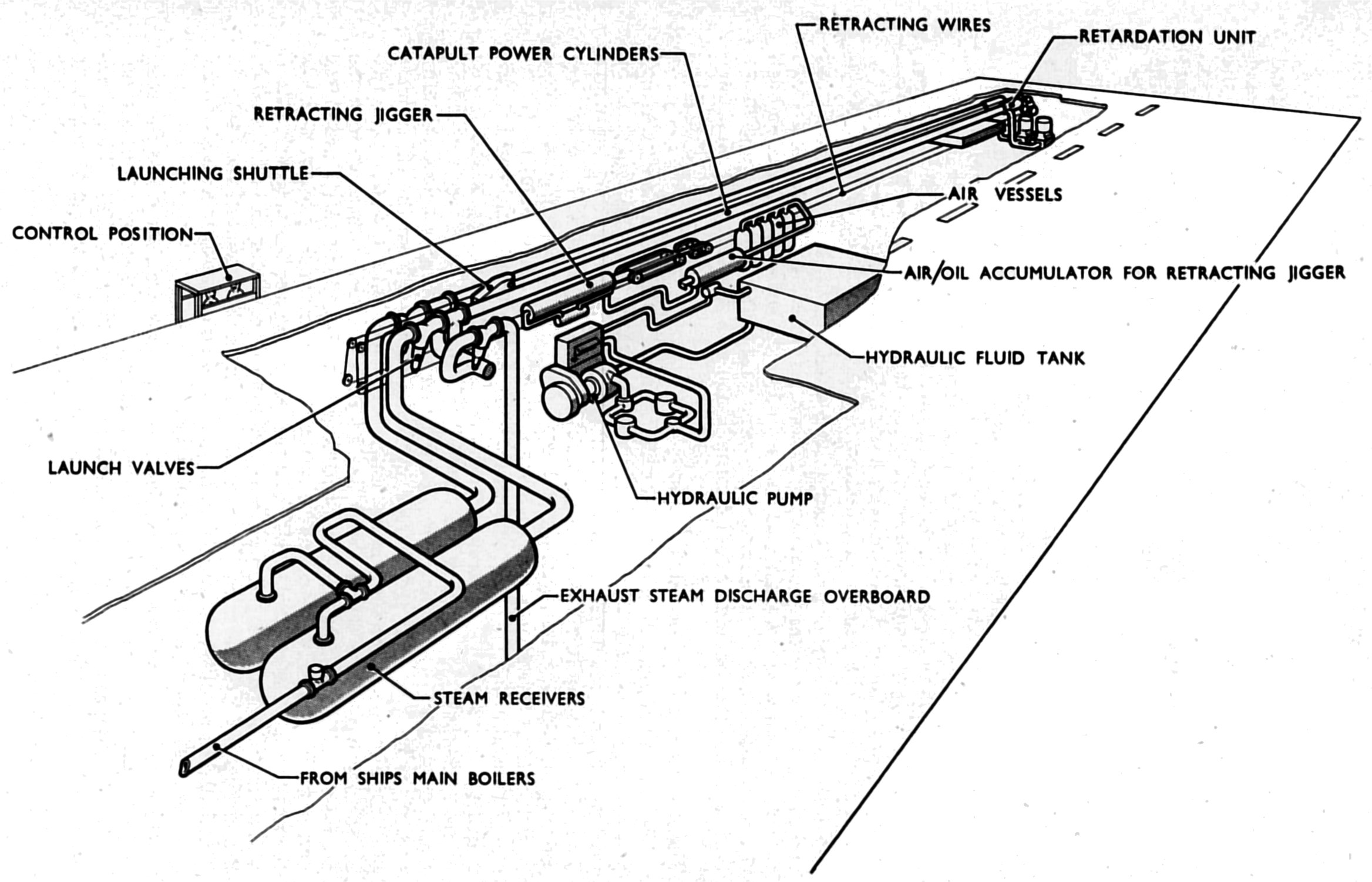
Fig. 5: Arrangement of a B.S.4 catapult in an aircraft carrier Click for enlargement.
The performance of the BS4 catapults to be fitted in Fleet carriers is very considerably greater than that of the most powerful hydro-pneumatic catapults. The heavier aircraft can be launched at greater speeds and lighter aircraft at much greater speeds. This latter is possible largely because the moving parts of the BS4 catapult are so much lighter than in hydro-pneumatic types, so that they can reasonably be brought to rest from much higher speeds at the end of the launch.
It should be noted that however powerful the catapult, the end speed it can give is limited by the acceleration which the aircraft (and aircrew) can withstand, and by the length of the catapult runway which the ship design will allow. Thus the shorter the catapult and the less the permissible acceleration, the less is the speed which can be attained. This is a matter of simple kinematics, which is part of the laws of nature and outwith the influence of catapult designers.
A prototype BS4 catapult was fitted in a temporary manner in H.M.S. Perseus and given extensive trials in 1951 and 1952. Some 1,560 launches were carried out, 355 light, 1,039 with deadloads and 166 with aircraft of nearly all available types, including Attackers, without mishap. In the early stages, as was to be expected, a number of troubles arose and were overcome by changes in detail design. Many possible improvements were also revealed and these have been incorporated in the final design for installation in ships. Without such prototype trials, and also shore trials carried out with the co-operation of the Armament Research Establishment, Ministry of Supply, it would not have been possible to be sure that the catapults being fitted in operational ships would be satisfactory and reliable, without very lengthy trials and subsequent modifications.
The catapult trials in H.M.S. Perseus included a visit to the United States in the spring of 1952, where the catapult was demonstrated so successfully that the U.S. Naval Authorities quickly decided to adopt the design and, as has appeared in the public press, have embarked on a programme of fitting it in U.S.N. aircraft carriers.
The characteristics to be expected from BS4 catapults in service can best be judged from measurements made during prototype trials in H.M.S. Perseus and from the experience of the pilots of aircraft launched from H.M.S. Perseus. Apart from the greater speeds the most notable feature, which was commented on by all pilots, was the very smooth acceleration as compared with hydro-pneumatic catapults. Although the acceleration was, in many cases, high, the effects felt were less disturbing due to the absence of jerks. This is because the force is solely provided and governed by an elastic medium, steam, with only a short connection to the aircraft, as compared with the relatively inelastic water and the long connection by ropes in the hydro-pneumatic catapult. The catapult is quiet in operation except that the retardation at the end of the stroke gives a severe blow to the ship's structure; below decks the impression given is very similar to that of a gun being fired. It was thought that the discharge of the catapult exhaust underwater might be noisy but in Perseus this was found not to be the case.
The BS4 catapults are designed for operation at a greater rate than BH5 or BH3 catapults.
A feature which must be of particular interest to aviators is reliability. The BS4 catapult contains many fewer moving parts than the BH3 or BH5 types. Great care has been taken in the design to promote reliability by good detail design and by making arrangements to facilitate maintenance. This latter is most important in catapults as in all machines. No machine will remain reliable without proper servicing and maintenance; this requires skilled work. and sufficient time to do it. Given proper maintenance it is confidently expected that, following the experience in Perseus after initial troubles were overcome, the BS4 catapult will prove entirely reliable.
Conclusion
That perfection is unattainable is as true of catapults as of any other device. The perfect catapult would be of negligible weight, occupy negligible space and require no maintenance. This cannot be claimed for the new catapult which, though lighter than corresponding hydro-pneumatic catapults, is still of considerable weight and occupies valuable space high up in the ship; nevertheless it is a considerable advance and, as with any novel device, it is at the beginning of its development so that further improvements and refinements in design may be expected.
It is not for the writer of this article to discuss the tactical effect of the greater performance offered by the BS4 catapult, both as regards freedom of carrier operations and in facilitating the use of higher performance aircraft, or in permitting reduction in the size and weight of aircraft for the same performance and endurance, but the benefits would appear to be considerable.