Marine propulsion – rotating nozzle
|
Modern azimuth thruster. |
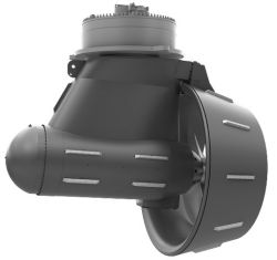
The idea of being able to steer a vessel by rotating the thrust of a propeller is generally considered as being a late twentieth century innovation. Many names have been used, including rotating nozzle, pod, azimuth thruster, and others.
They are mostly self contained, often electrically driven, and more often than not have a horizontal axis, but vertical axis examples do exist. A typical modern example is shown here.
The advantage of course is that you can go ahead or astern, port or starboard, without the need to disengage the drive or use any other form of rudder, just by rotating the unit about its vertical axis.
Origins
While cataloguing some Patent records, we discovered that John Eaton, of Belleville, Ontario, (Canada) had been granted U.S. Patent No. 21,825 dated 19 October 1858 – more that a century and a half ago. John Eaton appears to be one of the sons of a Loyalist family that moved to the Quinte region soon after the American Revolution, but details are elusive.
Eaton's invention is a vertical axis example, but further research has not found any other examples of a patent describing any other type of rotating nozzle. Nor have we found any proof that his idea was ever incorporated into a working vessel. The inventor describes, in the Report of the Commissioner of Patents for the year 1858 at page 69, his patent as:
|
An extract – click to enlarge. |
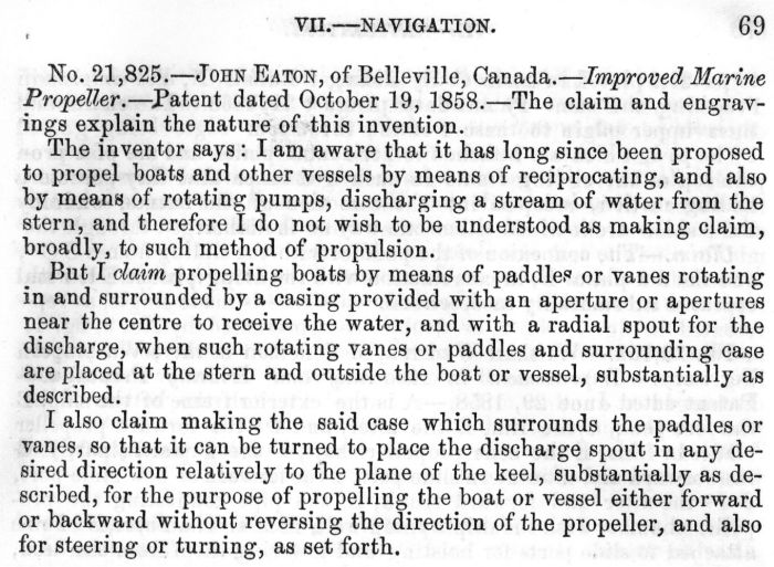
No. 21,825. – JOHN EATON, of Belleville, Canada. – Improved Marine Propeller. – Patent dated October 19, 1858. – The claim and engravings explain the nature of this invention.
The inventor says: I am aware that it has long since been proposed to propel boats and other vessels by means of reciprocating, and also by means of rotating pumps, discharging a stream of water from the stern, and therefore I do not wish to be understood as making claim, broadly, to such method of propulsion.
But I claim propelling boats by means of paddles or vanes rotating in and surrounded by a casing provided with an aperture or apertures near the centre to receive the water, and with a radial spout for the discharge, when such rotating vanes or paddles and surrounding case are placed at the stern and outside the boat or vessel, substantially as described.
I also claim making the said case which surrounds the paddles or vanes, so that it can be turned to place the discharge spout in any desired direction relatively to the plane of the keel, substantially as described, for the purpose of propelling the boat or vessel either forward or backward without reversing the direction of the propeller, and also for steering or turning, as set forth.
It is the last paragraph, and Eaton's use of the term "can be turned", that represents the earliest evidence of what is now common practice – a device allowing full and continuous 360º manoeuverability.
Details
As this is most probably the first description of an azimuth thruster, we include the original patent drawings (which you can click to enlarge in a new window) and the full technical description.
|
Drawings from patent.. |
UNITED STATES PATENT OFFICE.
JOHN EATON, OF BELLEVILLE, CANADA.
MARINE PROPELLER.
Specification of Letters Patent No. 21,825, dated October 19, 1858.
To all whom it may concern:
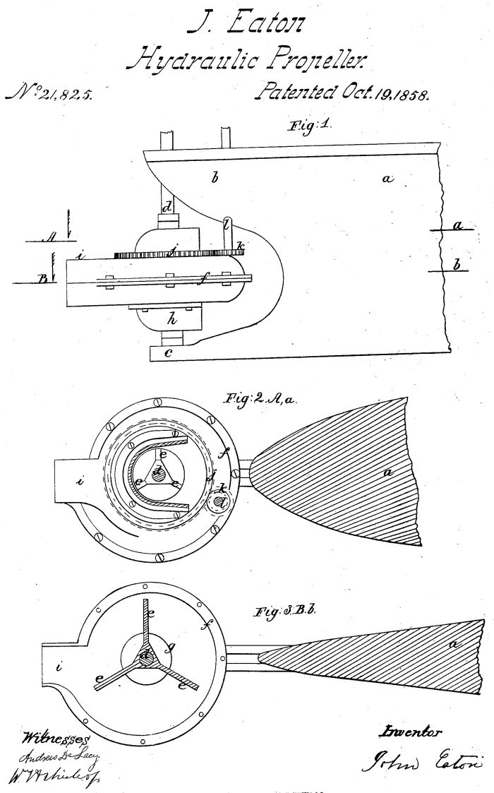
Be it known that I, JOHN EATON, of Belleville, county of Hastings, Canada, have invented certain new and useful Improvements in Propelling Vessels; and I do hereby declare that the following is a full, clear, and exact description thereof, reference being had to the accompanying drawings, making part of this specification, in which Figure l, is a side elevation of the rear part of a vessel with my improved propeller, and Figs. 2 and 3, horizontal sections taken in the planes of the lines A, a and B, b, of Fig. 1.
The same letters indicate like parts in all the figures.
My said invention relates to submerged propellers for canal boats, although applicable to other vessels, and to the steering and backing of boats or other vessels by the propeller without the necessity of reversing the engine or disconnecting it from the propeller.
The propeller is placed at the stern of the boat or other vessel, and consists of vanes or other paddles on a vertical rotating shaft, the said vanes being inclosed and rotated within a circular casing provided with an aperture or apertures at or near the shaft, and a radial spout or aperture at the periphery so that when the vanes or paddles are rotated by centrifugal action, the water shall enter the casing at or near the center and be forced out through the radial spout or aperture and thereby impel the boat or vessel. And the said case is so mounted and adapted that it can be turned to place its radial discharge spout or aperture in any direction desired relatively to the line of the keel; so that when turned from the stern the discharge of the water shall cause the boat or other vessel to be propelled in a straight line forward, when turned toward the stern the discharge of the water toward the bow shall back the boat or vessel; and when turned on either side of the plane of the keel, the discharge of the water will turn or steer the vessel in any direction dependent upon the angle which the radial discharge spout makes to the plane of the keel.
In the accompanying drawings (a) represents the stern portion of a boat or vessel, (b) the extension of the upper part of the stern back of the usual location of the stern post, and (c) an extension of the keelson and keel, provided on top and near its rear end with a suitable step for the lower journal or pivot of a vertical shaft (d) which extends up through, or into, the extension (b) of the overhanging stern, depending upon the location of the engine by which it is to be driven. This shaft near its lower end is provided with suitable vanes or paddles (e) such as are used in rotating blowers, and in some rotating pumps. The form represented in the drawings I have tried with success and believe to be the best adapted to the purpose, but as this makes no part of my invention others suited to the purpose may be substituted. These paddles or vanes are inclosed in a circular casing (f) mounted on the shaft but capable of turning thereon. The lower part of this casing rests and is suitably adapted to turn on the extension of the keelson (c). The lower plate of this casing (and if desired the upper plate may be formed in like manner) has an aperture (g) surrounding the shaft with a scoop formed plate (h) below inclosing the said aperture on one side and leaving it open on the other for the free entrance of water to the inside of the casing and around the shaft; and the said casing is formed with an aperture and radial spout (i) opposite to the aperture of the scoop formed plate (h). Both apertures should be of sufficient capacity, the one to supply water to the paddles or vanes and near the shaft as by the rotation they force it outward by centrifugal force against the periphery of the surrounding casing, and the other or the free escape, in the opposite direction, of the water, so impelled, through the radial spout. And although I prefer to admit the water to the center of the casing through the scoop like receiving spout, that it may enter on that side of the shaft directly opposite to the discharge, nevertheless that may be dispensed with and the water may be admitted to the casing through any suitable aperture or apertures provided it, or they, be near to the center, and of sufficient capacity for the free entrance of the water.
The top plate of the casing is provided with a circle of cogs, or a cog wheel (j)s which are engaged by the cogs of a pinion (k) on the lower end of a vertical shaft (l) extending up through the extension (b) of the stern, and there provided with a tiller or other suitable apparatus, by which it can be suitably and readily operated to turn the casing (f) so as to place the radial spout [?] in any desired direction relatively to the vertical plane of the keel; any other suitable means for turning the casing may be substituted.
From the foregoing it will be seen that when the shaft (d) is rotated with its vanes or paddles the water will enter the casing (f) through the central aperture and will be forced out by centrifugal action in a radial direction through the discharge spout (i), and that this discharge will tend to impel the boat or vessel in the reversed direction, so that by turning the casing to place the discharge spout in any desired direction the boat or vessel may be propelled forward or backward, and steered or turned without the use of any rudder, and more readily than can be effected by the use of any [?]. And what is of importance [?] the discharge spout being placed below the surface of the water boats can be propelled at a reasonable speed without such agitation of the surface as would be injurious to the banks of a canal.
[?] and therefore I do not Wish to be understood as making claim broadly to such method of propulsion. But what I do claim as my invention and desire to secure by Letters Patent is
1. Propelling boats by means of paddles or vanes rotating in and surrounded by a casing provided with an aperture or apertures near the center to receive the water, and with a radial-spout for the discharge, when such rotating vanes or paddles and surrounding case are placed at the stern and outside the boat or vessel substantially as described.
2. And I also claim making the said case which surrounds the paddles or vanes so that it can be turned to place the discharge spout in any desired direction relatively to the plane of the keel, substantially as described, for the purpose of propelling the boat or vessel either forward or backward without reversing the direction of the rotation of the propeller, and also for steering or turning, as set forth.
JOHN EATON.
Witnesses: WM. H. BISHOP, ANDREW DE LACY.
PA; 21 June 2014